1.Introduction
1.1Remote Operated Vehicle(ROV)
Remote Operated Vehicle (ROV), also known as underwater vehicle, working under extreme circumstance of underwater, which can dive into the water to substitute human to complete the underwater operation. Owing to the harsh and dangerous underwater environment and human's diving depth limitation, underwater vehicle has served as an important tool for the ocean exploitation. The way it works is that the staff of the supported vessel provides power via connecting the ROV umbilical cable, operates or controls the ROV, observes through underwater monitor, sonar and other special equipments, and conducts underwater operations through the manipulator.
The Competition examines the underwater comprehensive operation ability of the ROV, including scouting the aquaculture area and feeding, inspecting the hull along the prescribed route, collecting seabed ores, and underwater precise operation of supplying power and starting the seabed detector.
1.2 Venue and Site
Pool size: 10m× 5m, depth from 1m-1.3m, as shown below:
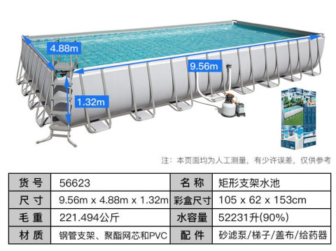
Figure 1 Site Diagram
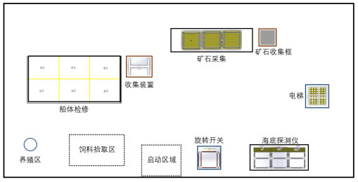
Figure 2 Competition Venue Diagram
1.3 ROV Specifications
A.Quantity: up to 1 (crawler walking is not allowed to avoid damaging the landform of the competition site)
B.The weight of the vehicle shall not exceed 25kg(weight of umbilical cable not included), otherwise it will not be allowed to participate in the competition.
C.Size: when the manipulator is retracted, the ROV shall be able to fit into a cube of 1000mm×1000mm×2000mm.
D.Number of Control Operators: no more than 2 persons and operators must be team members.
E.Number of Umbilical Cable Operators: no more than 2 persons
F.Finish time: 10 minutes
G.The manipulator need to sit in the designated position, cannot see the vehicle in the pool during operation, can communicate with the referee to ask the time, apply for stopping the game, etc.
2.Task
2.1 Delivering feeds
There is a seafood breeding area. In the ocean ranch, where the team members operate vehicle to drop feed into the breeding area.
There are two types of feed, both of which show negative buoyancy in water. One is in a feed container, and the other is a ball solid feed (with a "float") in a feed frame.
The breeding area is a cylinder with a diameter of 14cm and a height of 20cm, which is placed at the designated position at the bottom of the pool.
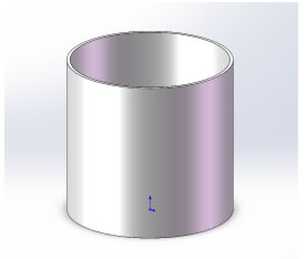
Figure 3 Breeding Area Diagram
The feed container is a 500mL plastic bottle with a counterweight and a negative buoyancy of no more than 5N in the water. It is placed in the feed picking area, as shown in the figure.
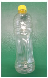
Figure 4 Feed Container Diagram
(no counterweight, certain beverage bottle)
The ball solid feed is made of "float", string and a golf ball. The feed should have negative buoyancy and sink in the bottom feed picking area. The amount of solid feed is 3 and placed in the feed frame in the feed picking area.
The "drift" is a pp board with a diameter of 150mm and a thickness of 10mm. There are two through holes with a diameter of 4mm and a center distance of 8mm, which are used to hold the string. And it shows positive buoyancy in the water.
The string should be soft and about 16cm long. A ring screw is attached to the golf ball to hold the string.
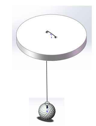
Figure 5 Ball Solid Feed Overall Diagram
The feed frame is a rectangular frame with the size of 34*15*15 (cm), which is composed of 20mmPVC tubes and net.
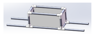
Figure 6 Feed Frame Diagram

Figure 7 Overall Side View Diagram ("float" slightly higher than the frame edge)
2.2 Inspection of Hull
Teams operate vehicles to inspect the underwater part of the hull, and point out the damaged part of the hull.
2.2.1Inspecting the Hull and Clean up the Damaged Part
The underwater part of the hull is a approximately 1.2m×2.4m blue rectangles, made up of 20mm PVC tubes. Red PVC pipe and white pipe fitting divide the rectangle into 6 areas, which are upper left, upper middle, upper right, lower left, lower middle and lower right. Each area is about 60cm×80cm rectangle, as shown in the picture.
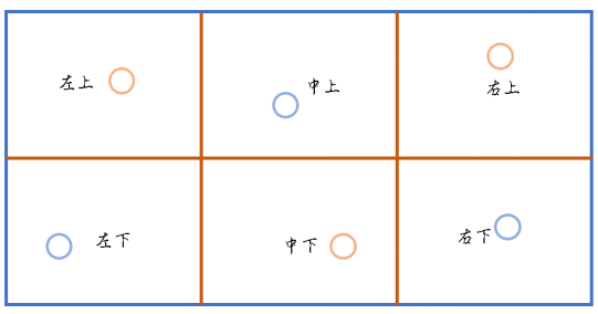
Figure 8 Diagram of the Hull
There will be 6 damaged points on the surface of the hull, which will be represented by red (blue) colored plastic rings (3 red, 3 blue). Each area has one damaged point, the corresponding color is shown in the figure above. In the process of inspection, the damaged object is picked up and hung into the collection device of the same color. Points are scored at the end of the competition based on the correct colored rings remained.
The plastic ring is made of pneumatic tubes and bolts, which have less negative buoyancy in the water and stand at the bottom of the pool. The collection device is made of 50mm diameter splicing PVC pipe, as shown in the figure.
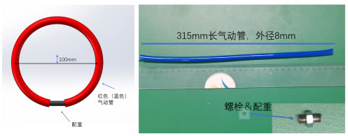
Figure 9 Damaged Point(Plastic Ring) Diagram
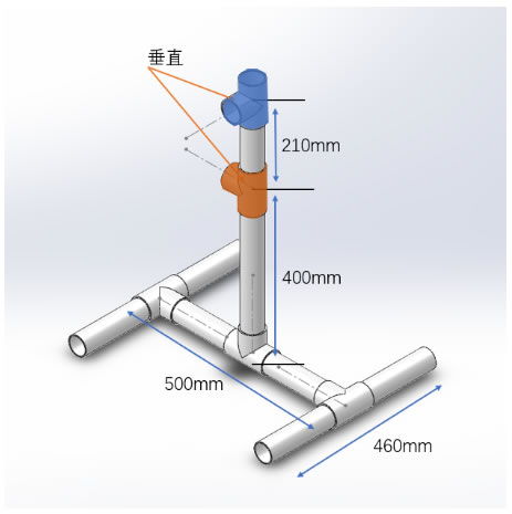
Figure 10 Collection Device Diagram
2.3 Collecting Seabed Ores
Different types of ores (golf of different colors) are distributed on the underwater ground and in reef gaps. Teams control the ROV to collect ores and drop them into the collection cells.
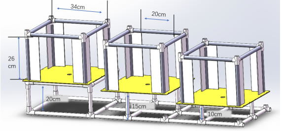
Figure 11 Reef Gaps Diagram
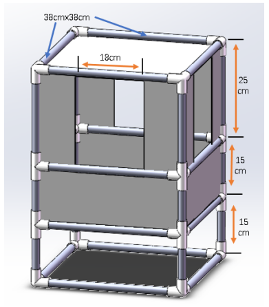
Figure 12 Collection Cell Diagram
2.4 Precise Operation
The team operators control the ROV to remove the connector from the “elevator”, insert the connector into the seabed detector which is then started by the rotary switch. In this task, the interface of the seabed detector is set in three types: large, medium and small, and different types of interfaces are inserted to obtain different scores.
Specific tasks:
1.Obtaining the connector from the “elevator”(a T-shaped plug about 24cm long and 12cm wide)
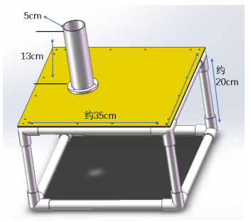
Figure 13 Elevator Diagram
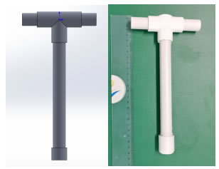
Figure 14 Connector(T-shaped Plug) Diagram
2.Inserting the connector into the seabed detector interface(small-medium-large: 30mm-60mm-90mm)

Figure 15 Seabed Detector Interface Diagram
3.Turning the rotary switch 180 degrees to start the seabed detector.
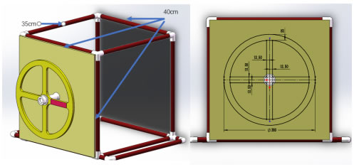
Figure 16 Rotary Switch Diagram
2.5 End of Competition
After completing all tasks, the vehicle immediately surfaces and team members apply for the end of the competition. When the vehicle surface, the minute timer for 10 minutes stops. The rest of time is converted into "remaining time bonus".
3.Scoring Criteria
The total score consists of operation scores completed within 10 minutes and bonus points. The bonus points can only be scored if all tasks are completed within 10 minutes. The competition result is sorted according to the total score. If the scores are the same, the team with lower quality wins.
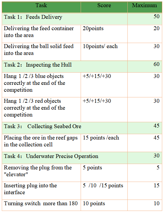
The above figures are for reference only, the competition is subject to the actual.
The organizing committee reserves the right of final interpretation.